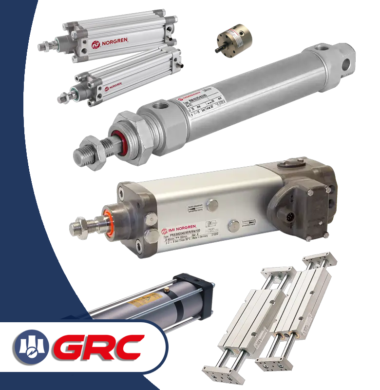


A pneumatic cylinder that “does not have enough force” is not necessarily damaged. In practice, the root cause is very often located upstream of the cylinder or in the way the cylinder force is transferred to the mechanism.
The pressure shown on the regulator gauge does not always match the pressure that is actually available inside the cylinder chamber during movement. Flow restrictions, undersized tubing, leaks, an incorrectly selected valve or side loads acting on the piston rod can all cause a cylinder to deliver insufficient force even though the system appears to have the correct operating pressure.
In this article, we explain the 7 most common causes of insufficient pneumatic cylinder force and show how to diagnose them systematically.
What determines the force of a pneumatic cylinder?
The basic relationship used to calculate the theoretical force generated by a pneumatic cylinder is:
F = p × A
where:
- F – theoretical cylinder force [N],
- p – pressure acting on the piston [Pa],
- A – effective piston area [m²].
In a real pneumatic system, however, the situation is more complex. Back pressure on the exhaust side and mechanical losses must also be taken into account.
The useful force can therefore be approximated as:
Fuseful ≈ p₁A₁ – p₂A₂ – Ffriction
This is why simply stating that “the system pressure is 6 bar” does not necessarily mean that the cylinder is actually producing the force corresponding to 6 bar.
A good example is the IMI Norgren RT/57250/M/50 pneumatic cylinder with a 50 mm bore. The manufacturer specifies a theoretical force of 1178 N at 6 bar.
Why does a pneumatic cylinder not produce enough force?
When diagnosing the problem, it is useful to treat the pneumatic system as a chain of components, each of which may introduce pressure loss or flow restriction:
compressed air supply → FRL → valve → tubing → cylinder → mechanical load
The most important rule is to perform measurements while the cylinder is actually moving, preferably during the part of the cycle with the highest load. A measurement taken while the machine is idle may fail to reveal the real problem.
1. Pressure drops during cylinder operation
One of the most common diagnostic mistakes is checking the pressure at the regulator while the system is stationary and assuming that the pneumatic supply is working correctly.
The real problem often becomes visible only when the cylinder starts moving. At that point, the required airflow increases significantly and restrictions become apparent in components such as:
- filters,
- pressure regulators,
- control valves,
- tubing,
- fittings,
- exhaust silencers.
Example
Assume the following measurements:
| Measurement point | Pressure at rest | Pressure during movement |
|---|---|---|
| FRL outlet | 6.0 bar | 6.0 bar |
| Valve inlet | 6.0 bar | 5.6 bar |
| Cylinder chamber | 6.0 bar | 4.8 bar |
In this example, the system loses as much as 1.2 bar between the air preparation unit and the cylinder during operation.
For a piston with a diameter of 50 mm, the piston area is approximately:
A = 0.0019635 m²
At 6 bar:
F ≈ 1178 N
At an actual pressure of 4.8 bar:
F ≈ 942 N
A 20% pressure drop therefore results in approximately a 20% reduction in theoretical cylinder force.
What should be checked?
- pressure before and after the FRL unit,
- filter element condition,
- pressure regulator flow capacity,
- pressure at the valve inlet,
- pressure directly at the cylinder port,
- pressure drop during the most demanding part of the machine cycle.
In pneumatic systems based on IMI Norgren components, air preparation solutions such as the Excelon Plus range can be used. However, correct component selection should always be based on the required airflow and permissible pressure drop, not only on the connection size.
2. Pneumatic tubing is too small
Another frequent cause of low cylinder force is insufficient tubing diameter.
The system may show the correct pressure while stationary, but during rapid movement, the cylinder chamber may not receive air quickly enough.
The most important factors include:
- internal tubing diameter,
- tubing length,
- number of bends,
- diameter reductions,
- quick couplings,
- kinked or damaged tubing.
Why can a few millimetres make such a large difference?
The cross-sectional area of tubing with a 4 mm internal diameter is approximately:
12.57 mm²
For tubing with a 6 mm internal diameter:
28.27 mm²
This means that the 6 mm tube has approximately 2.25 times the cross-sectional area.
This does not mean that the airflow will automatically be 2.25 times higher, because compressed gas flow also depends on tubing length, pressure, temperature and local flow restrictions. However, the comparison clearly demonstrates how significantly tubing diameter can affect system performance.
How should the problem be diagnosed?
- check the internal tubing diameter,
- measure the tubing length,
- check the number of reducers and fittings,
- compare dynamic pressure before the tubing and directly at the cylinder,
- if possible, perform a controlled test using shorter tubing with a larger internal diameter.
In many applications, positioning the valve as close as possible to the cylinder can also improve performance. Reducing the distance between the valve and actuator reduces the volume of compressed air that must be filled and exhausted during every cycle.
3. Leaks in the pneumatic system
A compressed air leak effectively acts as an additional air consumer.
Importantly, a small leak may have almost no visible effect when the machine is idle. The problem may only appear when several pneumatic consumers operate simultaneously.
Typical leak locations include:
- pneumatic fittings,
- damaged tubing,
- seals,
- valves,
- FRL components,
- cylinder piston seals.
How can leaks be located?
In simple systems, a leak detection fluid or soapy water can be used. In larger industrial installations, more effective methods include:
- ultrasonic leak detectors,
- acoustic imaging cameras,
- airflow measurement.
Acoustic cameras are increasingly used in industrial compressed air systems because they can help identify leaks that may not yet be clearly audible.
If the cylinder itself is suspected, it is also important to check for internal leakage between the two cylinder chambers.
4. Incorrectly selected pneumatic valve
A pneumatic valve may switch correctly and still restrict cylinder performance.
The key parameter is not only the valve function, but also its ability to provide sufficient airflow at an acceptable pressure drop.
An undersized valve can create a characteristic situation:
- the system reaches the expected pressure after the cylinder stops,
- pressure drops significantly while the cylinder is moving,
- the cylinder slows down or cannot generate the required force.
What should be verified?
- valve function – for example 3/2, 5/2 or 5/3,
- nominal flow rate,
- Kv coefficient,
- port size,
- operating pressure range,
- pressure drop across the valve,
- exhaust side restrictions.
The exhaust silencer should not be ignored. A heavily contaminated silencer can generate back pressure on the exhaust side, which directly reduces the useful force produced by the cylinder.
For comparison, an example IMI Norgren VM10 valve can provide a flow rate of approximately 430 l/min, while certain variants from the VM15 range can reach approximately 900-1000 l/min.
This does not mean that a larger valve is always better. Valve size should be selected according to the required airflow, cylinder speed and acceptable pressure losses in the application.
5. Friction, misalignment and side loading of the piston rod
Not every cylinder force problem is caused by the pneumatic system itself.
A linear pneumatic cylinder is primarily designed to generate axial movement. If the machine design applies significant side forces to the piston rod, friction increases and wear of seals, bushings and guiding components accelerates.
Typical mechanical problems include:
- misaligned cylinder mounting,
- side loading of the piston rod,
- lack of external guidance,
- distorted machine components,
- worn guides,
- damaged piston rod surfaces.
Example
If a cylinder theoretically generates 1178 N, but 180 N is required simply to overcome friction and mechanical resistance, the force remaining for the actual load is:
1178 N – 180 N = 998 N
In a real machine, these mechanical losses should be measured rather than assumed.
How should the mechanical side be diagnosed?
- safely disconnect the mechanical load from the cylinder,
- check the movement of the cylinder alone,
- compare it with the movement of the complete mechanism,
- inspect mounting alignment,
- check the piston rod and guides,
- use external guidance where necessary.
In applications exposed to significant side loads, guided units or external linear guides can be used to separate the guiding function from the pneumatic cylinder itself.
6. Incorrect cylinder bore size
Sometimes the pneumatic system operates correctly, but the cylinder itself has simply been undersized.
A common engineering mistake is calculating the required bore based on nominal plant pressure, for example 6 bar, instead of using the minimum actual pressure available at the cylinder during the most demanding part of the operating cycle.
Example of cylinder bore calculation
Assume that the mechanism requires:
F = 1000 N
and the actual available pressure at the cylinder is:
p = 5 bar
The minimum theoretical piston diameter is approximately:
Dmin ≈ 50.46 mm
A 50 mm cylinder operating at 5 bar generates theoretically only:
982 N
This means that even under ideal conditions, the cylinder is already too small because friction, back pressure and a design safety margin have not yet been included.
In such a case, the next standard bore size – for example 63 mm – may need to be considered after all operating conditions have been evaluated.
IMI Norgren offers, among others, pneumatic cylinders compliant with ISO 15552 in multiple standard bore sizes, making it possible to select an actuator suited to the actual force requirement.
7. Poor compressed air quality
The final cause often develops gradually. Contaminated or improperly prepared compressed air may slowly degrade pneumatic components until a noticeable performance problem appears.
The most important contaminants include:
- water and condensate,
- solid particles,
- oil contamination,
- corrosion products from the compressed air network.
These contaminants may cause:
- accelerated seal wear,
- increased friction,
- valve sticking,
- corrosion,
- irregular cylinder movement,
- increased pressure drops.
The ISO 8573-1 standard classifies compressed air purity in terms of particles, water and oil.
What should be checked?
- filter condition,
- presence of condensate,
- operation of automatic drains,
- pressure drop across the filter,
- dew point in demanding applications,
- required compressed air purity class.
This does not mean that the finest possible filtration should always be used. Every filter introduces a certain flow resistance. Therefore, filtration level must be selected according to both process requirements and the required airflow.
How to diagnose insufficient pneumatic cylinder force step by step
Instead of immediately replacing the cylinder with a larger one, it is better to follow a structured diagnostic process.
- Measure the dynamic supply pressure.
- Measure the pressure directly at the cylinder during movement.
- Compare the measurements and identify where the largest pressure drop occurs.
- Check tubing diameter and length.
- Verify valve flow capacity and technical parameters.
- Inspect the system for leaks.
- Check exhaust silencers and exhaust restrictions.
- Inspect mechanical alignment and side loads.
- Compare the required force with the actual cylinder bore size.
- Verify compressed air quality.
Practical maintenance checklist
| Inspection point | What should be checked? | Possible corrective action |
|---|---|---|
| Pressure | pressure during machine operation | check air supply and regulator |
| FRL | pressure drop under flow | service filter or select a higher-flow unit |
| Tubing | diameter, length and reductions | increase diameter or shorten tubing |
| Valve | flow rate, Kv, ports and exhaust | select a correctly sized valve |
| Leaks | fittings, tubing and valves | repair or replace leaking components |
| Cylinder | internal leakage and piston rod condition | service or replace the cylinder |
| Mechanics | alignment and side loading | improve mounting or guidance |
| Cylinder bore | required force versus available force | select the correct cylinder size |
| Air quality | water, particles and oil | improve compressed air preparation |
A larger cylinder is not always the right solution
One of the most expensive troubleshooting mistakes is immediately replacing a pneumatic cylinder with a larger model.
If the existing cylinder was correctly selected for 6 bar but only receives 4.8 bar during operation, installing a larger actuator may simply mask the real problem elsewhere in the pneumatic system.
On the other hand, if calculations show that even the theoretical cylinder force at the actual operating pressure is lower than the required force, a better valve or larger tubing will not solve the problem. In that case, increasing the cylinder bore may be necessary.
IMI Norgren pneumatic diagnostics with GRC
An effective diagnosis of a pneumatic cylinder should answer four key questions:
- What pressure actually reaches the cylinder during operation?
- Can the pneumatic system provide the required airflow?
- How much force is being lost due to mechanical resistance?
- Is the cylinder bore correctly sized for the actual load?
Only after these questions have been answered should decisions be made regarding replacement of the air preparation unit, tubing, valve, guiding system or the cylinder itself.
GRC provides technical support in the selection, diagnostics and servicing of IMI Norgren pneumatic solutions. If the problem concerns cylinder sizing, pneumatic valves, air preparation units or the operation of an existing pneumatic installation, our technical team can support the diagnosis and selection of suitable components.
GRC Sp. z o.o.
Service: +48 730 032 730
E-mail: serwis@grc.pl
Sales: +48 509 226 802
E-mail: biuro@grc.pl
Frequently Asked Questions
Why does a pneumatic cylinder have insufficient force even when the pressure appears correct?
The pressure measured at the regulator may differ significantly from the pressure available at the cylinder during movement. Flow restrictions in tubing, valves, filters and fittings may cause dynamic pressure losses.
How can pneumatic cylinder force be increased?
Cylinder force can be increased by increasing the actual operating pressure within the permitted range or by using a cylinder with a larger bore. Before doing so, pressure drops, leakage and excessive friction should be eliminated.
How do you calculate pneumatic cylinder force?
The theoretical force can be calculated using F = p × A, where p is the pressure acting on the piston and A is the effective piston area. In practice, friction and back pressure should also be considered.
Can undersized tubing reduce pneumatic cylinder force?
Yes. Tubing with an insufficient internal diameter restricts airflow and may cause a significant pressure drop at the cylinder during movement.
Do compressed air leaks affect cylinder force?
Yes. Leaks increase overall compressed air demand and can cause pressure drops, particularly when several pneumatic devices operate simultaneously.
How can I tell whether a pneumatic valve is too small for the cylinder?
Compare the required airflow with the valve specifications and measure the pressure drop across the valve during cylinder movement. A significant dynamic pressure difference may indicate insufficient valve flow capacity.
How does compressed air quality affect pneumatic cylinders?
Water, oil and solid particles can accelerate seal wear, increase friction, cause corrosion and interfere with the correct operation of valves and cylinders.